
Details
1、 Zero power resistance value (Rt)
When measuring the resistance value of a thermistor at a specified temperature, the change in resistance value caused by the internal heating of the resistor body is negligible compared to the total measurement error, and the resistance value measured at this time is the zero power resistance value.
2、 Rated zero power resistance value (R25)
The value marked on the thermistor, unless otherwise specified, this value is the nominal value at a reference temperature of 25°C.
3、 Resistance value expression
The resistance value is expressed in scientific notation: resistance value = the first two real numbers 01-99 x the value of the third value as a power with a base of 10, in ohms. Example: 222 = 22 x 102Ω, 103 = 10 x 103Ω.
4、 B-value
B-value is expressed by the formula
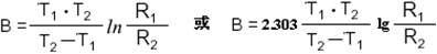
Where
B: constant, in K.
R1: resistance value at a temperature of T1, in Ω.
R2: resistance value in Ω at a temperature of T2.
T1: 298.15K (+25°C).
T2: 323.15K (+50°C).
Note: Unless otherwise stated, B-values in this book refer to B25/50 (i.e. B-value for 25°C/50°C)
5. B-value categories
To simplify the B-value categories, B1 refers to B25/50, B2 refers to B25/85 and B3 refers to other special application conditions for temperature taking.
6. Dissipation factor (δ)
In the specified ambient temperature, the ratio of the change in power dissipation in the thermistor to the corresponding temperature change in the thermistor body (expressed in mW/°C).
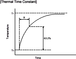
7、 Thermal time constant(τ)
The time required for the thermistor to change to 63.2% of the initial and final temperature difference when there is a sudden change in temperature under zero power conditions.
8、 Operating Temperature Rang
Refers to the ambient temperature range over which the thermistor maintains zero power over a long period of time. Limits the maximum and minimum values of the operating temperature.
9、 Resistance-Temperature Characteristics
The dependence between the zero power resistance value of a thermistor and its body temperature.
10、 Voltage-current characteristics
The dependence between the terminal voltage of the thermistor (DC or 40-60HZ AC) and its applied steady-state current at 25°C (or at the specified temperature) in still air.
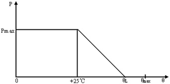
11、 Maximum rated power (Pmax)
The maximum power consumption that can be applied to the thermistor for a long period of time at an ambient temperature of 25°C (or at a specified temperature). When the ambient temperature exceeds 25°C, the rated power decreases linearly and at a certain ambient temperature condition the rated power will be linearly reduced to zero.
12. Error levels
In this paper, the resistance and B-value error levels are expressed in a common way, i.e. F means ±1%, G means ±2%, H means ±3%, J means ±5%, K means ±10%, L means ±15% and M means ±20%.
13、 Packaging method
In this article, B indicates that the shipped products are packaged in bulk, and T indicates that the shipped products are packaged in braided tape.
14、 Thermistor Legend
Unless otherwise specified, the thermistors in this document are shown as legends in the relevant circuit diagrams .
.
Contact Us
Fax: +86-769-83428283
Email: sss@sensicom.net
Add.: Qiaotou Town, Dongguan City, Guangdong Province, China

Follow Us
Copyright 2023 Dongguan Sensicom Electronic Technology Co., Ltd. 粤ICP备05029898号 网站建设:中企动力 东莞 SEO